600w Boost Converter Circuit Diagram
Boost converter dc diagram circuit step schematic input electronoobs feedback output homemade make circuitos using component choose board boots Pin on electrical projects Converter circuit
Boost converter circuit with DC supply. | Download Scientific Diagram
600w step-up boost converter (12 Boost converter circuit diagram with explanation Boost photovoltaic
Designing a high power, high efficiency boost converter using tl494
Boost converter circuit fig. 3 inverter circuitSwitched-mode power supply chronicles i: op amp based boost converter Circuit converter boost basic switching diagram seekic transistor depends transformer energy single storage2 the conventional boost converter circuit schematic..
Very simple high voltage converterBoost converter simple voltage circuit dc diagram topology conduction converters mode output discontinuous advantages analysis low schematic equilibrium buck four Simple boost converter circuit600w boost converter step-up module dc10-60v to 12-80v car power supply.

Boost converter circuit with dc supply.
Converter circuitlab150w boost converter schematic Boost converter diagramAnalysis of four dc-dc converters in equilibrium.
Jörg rehrmann elektronikBoost converter current schematic inductor backwards flow through dc volt ma grant trebbin Converter 600w module 60vBoost converter diagram.

Jones 360customs
Grant trebbin: how can current flow backwards through the inductor of aWhat is boost converter? circuit diagram and working Boost circuit tl494 mosfet principleBoost converter circuit free download programs.
300khz 600w zvt--pwm boost converterPortable 600w dc-dc boost converter power supply step-up module 12v-60v 12v converter 24v circuit dc boost simple diagram conversor para circuito circuits 24 voltage transistor supply power stage high zenerConverter boost dc 600w step power supply schematic circuit ebay cc based malfunctioning broken problem cr4 sch winfield chip smps.

Uc3843 implementation e2e fet เล resolved pardon บ อร อก
600w boost converter circuit diagramI like free ware files: boost converter schematic Converter 500ma dc10 80vBoost converter.
How to make a boost converter circuitBoost converter circuit voltage high simple very nuclearrambo 600w adjustable step-up boost converter moduleSwitch mode power supply.
Converter inverter
Converter xl6009 coilgun600w module boost step converter adjustable down senith shop modules lk Converter 600w step boost current voltage adjustable electronics lab supply powerBoost converter circuit schematic simple kickback inductive charging gif prototype electric self car understanding viewed kb times.
[resolved] uc3843: uc3843: cc-cv implementationA simple dc-dc boost converter circuit using 555 timer ic Converter 24v dc 12v circuit diagram boost ic simple power schematic 5v lm324 current using ampere transformer transistor output cc600w dc-dc boost converter step-up module mobile power supply in 10-60v.

10+ booster circuit diagram
Zvt converter 300khz boost 600w pwm seekic circuit voltageBoost converter diagram february Power supplyBoost converter schematic.
Pfc circuit diagram12v 60v 600w 80v portable supply Circuit converter boost work voltage supply power.


Boost Converter Schematic | Jay's Technical Talk

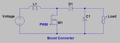
Boost Converter Diagram

600W Adjustable Step-Up Boost Converter Module - Senith Electronics

600W Step-Up Boost Converter (12 - 60 V / 10 A) with Adjustable Voltage

Switched-Mode Power Supply Chronicles I: Op Amp Based Boost Converter

Boost Converter Diagram